


Why a Wheelbarrow Is a Second-Class Lever

By OnelROR Editorial Team · November 17, 2026 · 3 min read
A wheelbarrow’s wheel is easy to notice. Its other useful feature is the arrangement of the tray and handles. When the rear legs are off the ground, the handles let the user support the load through a lever rather than carry all its weight directly.
Locate three positions
In the familiar front-wheel design considered here, the wheel’s axle provides the pivot. The combined weight of the wheelbarrow and its contents acts between that pivot and the hands at the handles. OpenStax uses this arrangement to explain the wheelbarrow’s mechanical advantage. [1]
TeachEngineering calls this a second-class lever: the load lies between the pivot and the effort. “Second-class” names their order, not a quality grade or a product rating. A seesaw has a different arrangement, with its pivot between the load and effort. [2]
Diagram key: The wheel axle is the pivot. Combined wheelbarrow-and-content weight acts between the pivot and upward effort at the handles. The rear legs are raised.
Compare the moment arms
Distance matters as well as order. For vertical forces, the relevant moment arms are the horizontal distances from the pivot to the forces’ lines of action. A longer effort arm can balance the same load with a smaller force. [1]
Consider an invented, stationary model. Its combined downward weight is 300 newtons, acting 0.40 metres behind the axle. The hands act upward 1.20 metres behind it. Balancing their turning effects gives:
Hand force × 1.20 = 300 × 0.40
The hand force is 100 newtons. The wheel supports the remaining 200 newtons. These numbers illustrate equilibrium; they are not measurements or a loading recommendation for a real wheelbarrow.

Diagram key: The load arm is 0.40 m and the effort arm is 1.20 m. Each turning effect is 120 N·m: 300 × 0.40 = 100 × 1.20. Measure perpendicular to the vertical lines of action, not along a sloping handle.
Keep the model’s limits
The weight has not disappeared. Support is shared between the hands and wheel, and changing where the combined weight acts changes the calculation. With the same hand position, a longer load arm requires a larger hand force. [1][2]
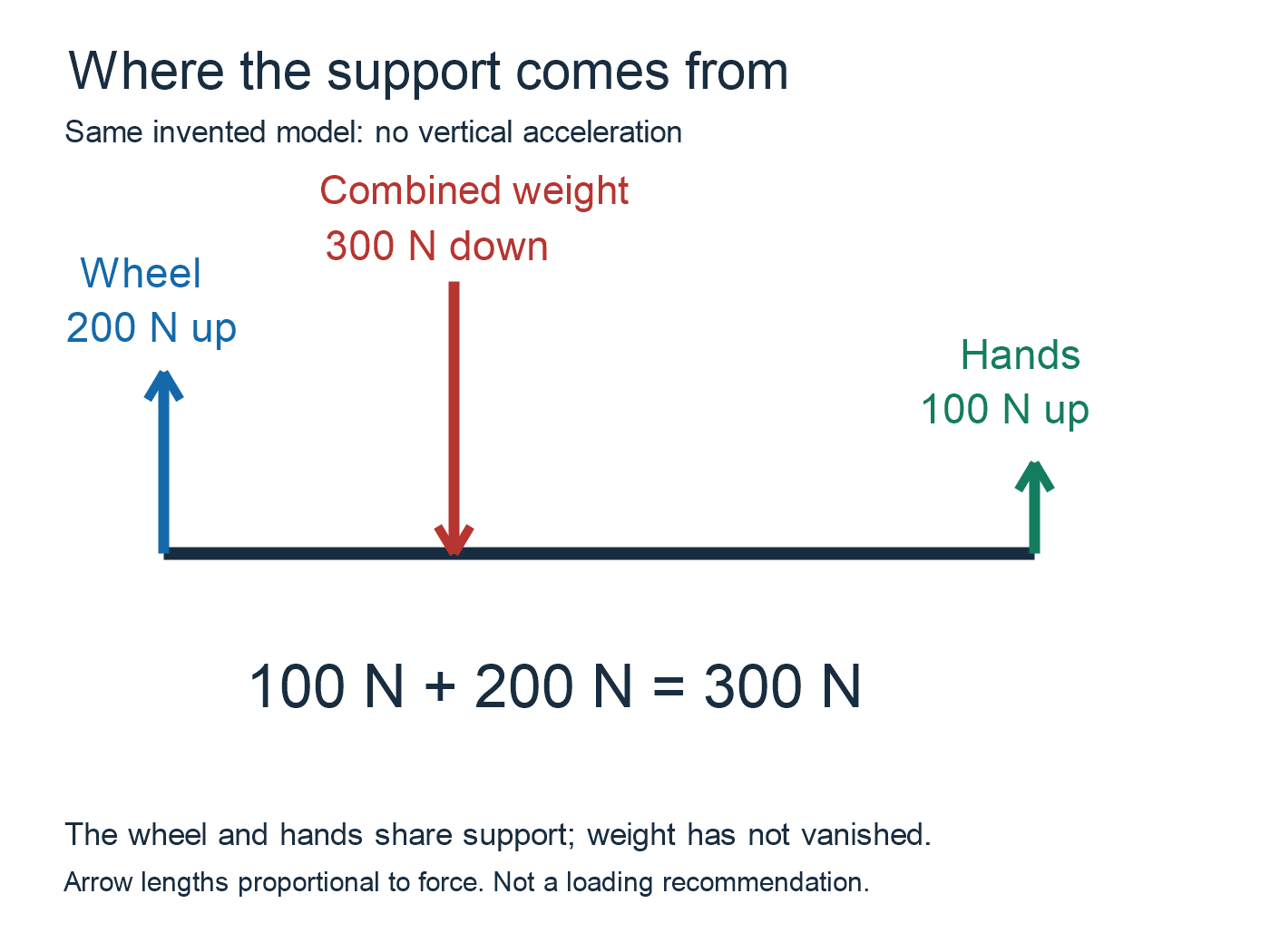
Diagram key: Upward forces from the hands (100 N) and wheel (200 N) balance the combined downward weight (300 N). Net vertical force is zero. The illustrated arrows have proportional lengths; these are invented values, not a product rating.
This is a side-view explanation with vertical forces and no acceleration. It does not assess sideways tipping, uneven ground or a manufacturer’s load limit. Use the diagram to identify the pivot, load and effort before interpreting the force arrows.
Sources
- OpenStax, College Physics 2e: 9.5 Simple Machines, lever discussion, Figure 9.22 and Example 9.3.
- TeachEngineering, University of Colorado Boulder: Levers That Lift, Mechanical Advantage and Lever sections.